DIY Ribbon Microphone - Frequency Response
So, why and how does the cross-section of a motor affect the frequency response? The answer is in phase shift of a sound wave. When the sound wave moves through the air, it continuously changes in phase in certain fixed points. In our case, the points of interest are the point right in front of the ribbon and the point right behind the ribbon.
Ribbon microphones are mostly designed as pressure-gradient microphones. A diaphragm (a ribbon in our case) of a pressure-gradient microphone gets motivated not by the pressure of the soundwave itself, but by the pressure difference between the front and the back of the diaphragm. As it takes some finite time for a wave to travel around the motor frame, its phase shifts along the way.
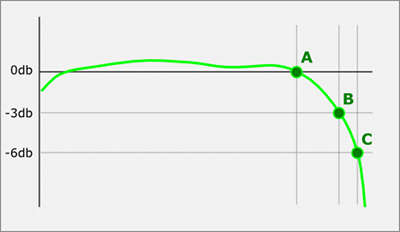
Figure 1: a typical frequency plot of a ribbon microphone. Point A is the end of the flat response
Point B is a 3dB signal drop
Point C is a 6dB signal drop.
The actual A, B and C frequencies depend on the geometry of the particular ribbon motor (see figure 2)
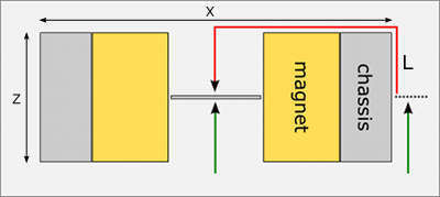
Figure 2: a ribbon microphone motor, view from above. The green line shows the path of a sound wave before it gets delayed by the chassis. The red line (L) shows the length of the vawe’s path to the backside of the ribbon. The sound wave travels the half-thickness of the motor twice and a half-width once, so the approximate length of the path can be calculated using formula: L = Z + X/2, where Z is the thickness of a motor and X is its width (measured in the middle of the height if the width is not constant, f.ex. if the motor has a sand-clock shape).
The proportion of this change varies with the frequency. Low frequency waves are very long, measured in meters (100 Hz wave is 3.43 meters or 11.25 feet long), so the proportion of displacement relatively to its wavelength is very small, but on the other hand, the energy of a low frequency wave is huge, so even the smallest change in phase will cause a significant difference in pressure on both sides of a ribbon, thus displacing it.
High frequency waves carry very low energy, but they are short, measured in centimeters (5 kHz wave is 6.86 cm or 2.70 inches long), so while the motive force is low, the proportion of the distance around the motor is significant in relation to the wavelength, so the phase shift will be big and the proportional pressure difference between the sides of a ribbon will be much higher, thus still providing enough energy to displace the foil. Everything is very smart in nature, isn’t it?
Physics engineers may throw rock at me, but for better understanding I would roughly say, that the force, that moves the ribbon is in some way equal to the phase difference between front and back multiplied by the energy of a wave (ribbon motion = phase shift * wave energy). Low frequency waves carry huge energy, but the phase shift is very small, on the other hand, high frequency waves carry very small energy, but phase shift if huge, so the flat part of the frequency band equalizes naturally this way.
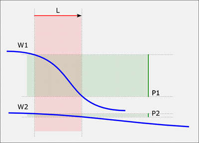
Figure 3: the dependence of a phase shift from a wavelength over a given distance. Red line (L) is the length of the path from the front to the back of a ribbon (see figure 2).
L: the length of a sound path
W1: high frequency wave
W2: low frequency wave
P1: phase shift in a high frequency wave
P2: phase shift in a low frequency wave
W – wavelength
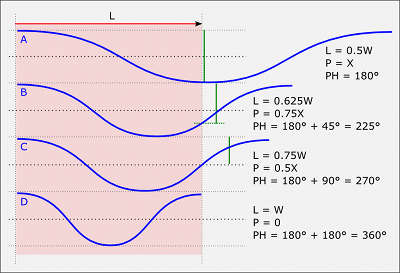
P – pressure difference between the front and the back of a ribbon (green lines), where X = maximum possible relative pressure difference
PH – phase shift between the front and the back of a ribbon
A: end of flat response
B: 3 db drop
C: 6 db drop
D: termination freq
High Frequency Response Calculation
The point of the total zero is reached, when the wave makes a full cycle between the front and the back. The pressure on both sides becomes the same at the moment. Therefore, the frequency when the wavelength becomes equal to the length of the path (see Figure 2) is our HF null point. For example, in our RE-423 motors, the length of the path is approx. 14 mm, so the termination frequency is 24.5 kHz. But, in fact, this is not the number, which is interesting for us, because the actual roll-off starts far beyond that point. After the point of 180 degree phase shift, additional shift by 45 degrees (1/8 of wavelength) will cause the signal level drop by 3 db (which is the standard threshold in defining the frequency response of a microphone) and after another 45 degrees (90 in total) the signal will drop by another 3 db (6 db in total, meaning voltage drop by 50%). In case of same 14 mm path the 3 db drop point should be at 15.3 kHz and 6db drop point at 18.3 kHz, with the flat response until 180 degree point at 12.3 kHz.
To make the math more clear (see figure 4): the 180 degree point (the end of flat part of response) is the half (4/8) of the wavelength, so we have to find out the frequency with the wavelength of twice the sound path length. For example, if we have the wave path length of 20 mm, the response will be flat until the wavelength reaches 40 mm, which is equivalent to 8.6 kHz. The 3 db drop point is located at 5/8 of the wavelength (180 degrees is 4/8 + 45 degrees, which is 1/8 = 5/8), so the signal will drop by 3 db, when the the sound path length is 5/8 or 0.625 of the wavelength. We have to divide the path length by 0.625. With 20 mm path length it is 20/0.625 = 32 mm, which is equivalent to 10.7 kHz. Thus, we can define, that the ribbon microphone with the length of sound path of 20 mm will have the frequency response up to 10.7 kHz before -3 db output signal drop.
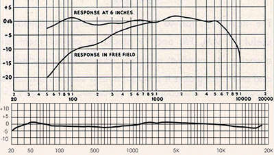
Figure 5: the comparison of a frequency response in classical (top) and modern (bottom) ribbon microphones. The Significant path length reduction due to invention of very powerful Neodymium magnets resulted in much wider and flatter response.
RCA SK-46 and Royer R-121 as examples.