Illustrated step-by-step guide to the assembly process of the RM-7 DIY Ribbon Mic Kit.
Published: 2019.10.24, last updated: 2019.10.24, author: Artur Fisher.
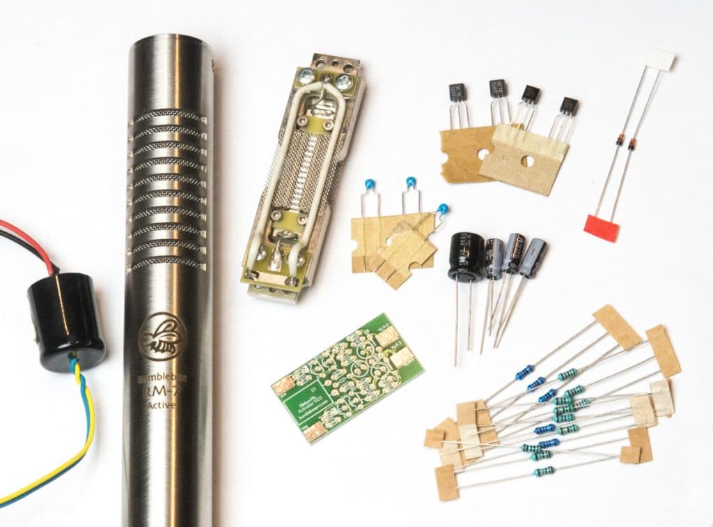
What's In The Box
RM-7 Ribbon Microphone Body with a grill and an XLR insert with gold-plated pins
RE-432 Ribbon Microphone Motor with 1.2u ribbon
RTX-28 Toroidal Transformer
Bb-A20 Ribbon Mic Activator Kit
What else is required:
Soldering iron
Some solder and flux
Screwdriver with a 5/64 Hex head or Torx TH8 head
A small piece of wire for a jumper (solid wire works best, you can use a resistor lead)
Some electrical tape
A tiny piece of scotch tape might be needed
Before You Begin:
If you’ve ordered the Bb-A20 Ribbon Mic Activator pre-assembled, you can proceed right away. If your mic activator came as a kit, please assemble it first and then proceed according to this manual.
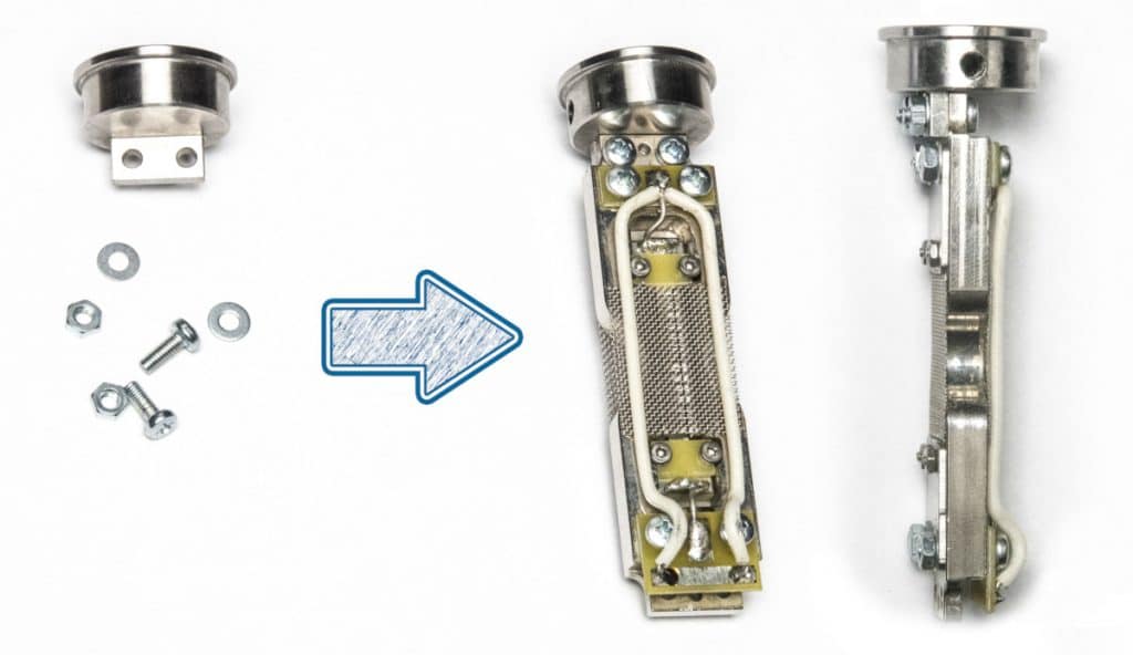
1. Fix The Ribbon Mic Motor to The Top Cap with Supplied Screws
Use the supplied M3 screws to fix the motor on the top cap. See the correct motor alignment on the pictures below. When fixed, put the motor aside proceed to the next step.
Warning: make sure your workplace is perfectly clean and all the metal objects are well away.
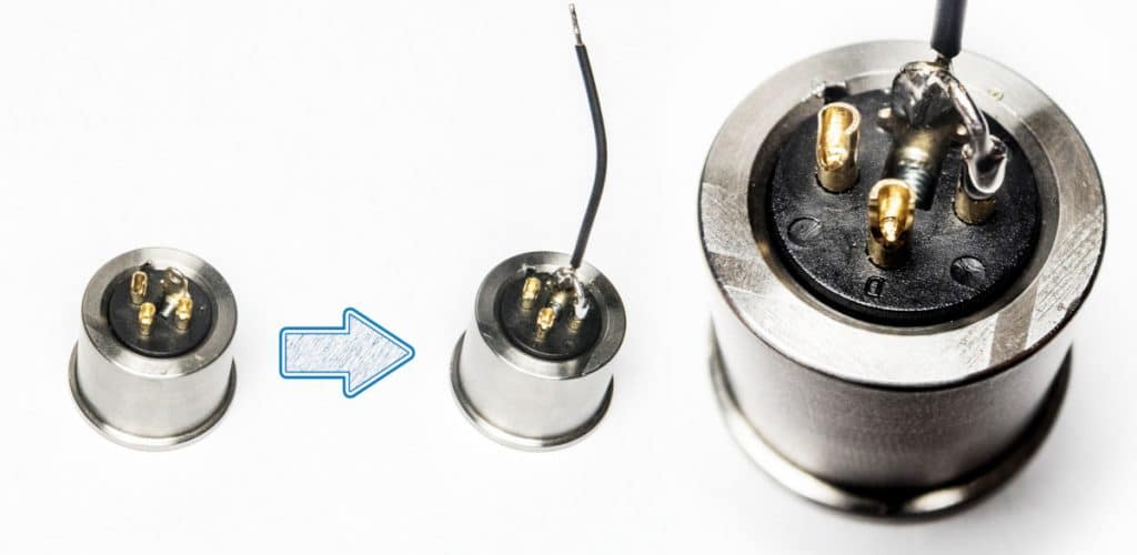
2. Solder a Jumper and a Piece of a Wire To The XLR Socket
Use a piece of a solid wire (not included) to make a jumper between the XLR socket pin-1 and a ground pin. This operation connects the microphone body to the cable shield. Solder the included piece of wire (can be of any color, not mandatory black) to ground pin.
Advice:plug in the female XLR of any cable into the mic XLR socket while soldering. It will work as a heat sink and will secure the position of pins in case if you overheat the point and plastic starts melting.
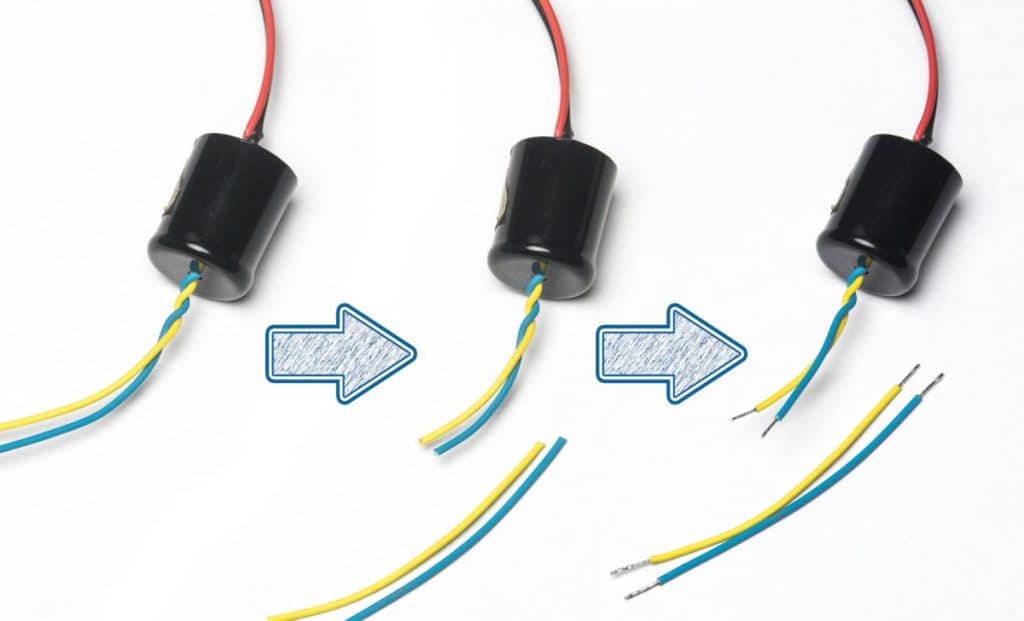
3. Cut, Strip and Tin The Transformer Wires
Cut off slightly more than a half of length from yellow and blue wires. Strip and tin the ends as shown on the picture below. These wires will be used to connect the activator PCB to XLR socket.
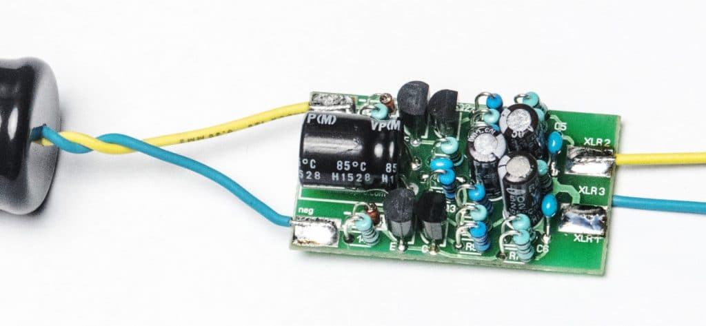
4. Solder The Transformer and Wires To The Activator PCB
Solder the transformer to the input of the activator PCB (it should be assembled at this point). The yellow wire goes to the “pos” pad and the blue wire goes to “neg” pad. Now solder the wires you’ve cut off to the output of the activator PCB. The yellow wire goes to “XLR2” pad and the blue wire goes to “XLR3” pad (on the back side of the PCB).
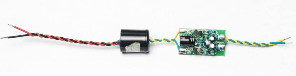
5. Twist All The Wires Tightly
Twist all the wires tightly. The direction of twisting does not matter. The proper twisting may be critical for the proper interference immunity.
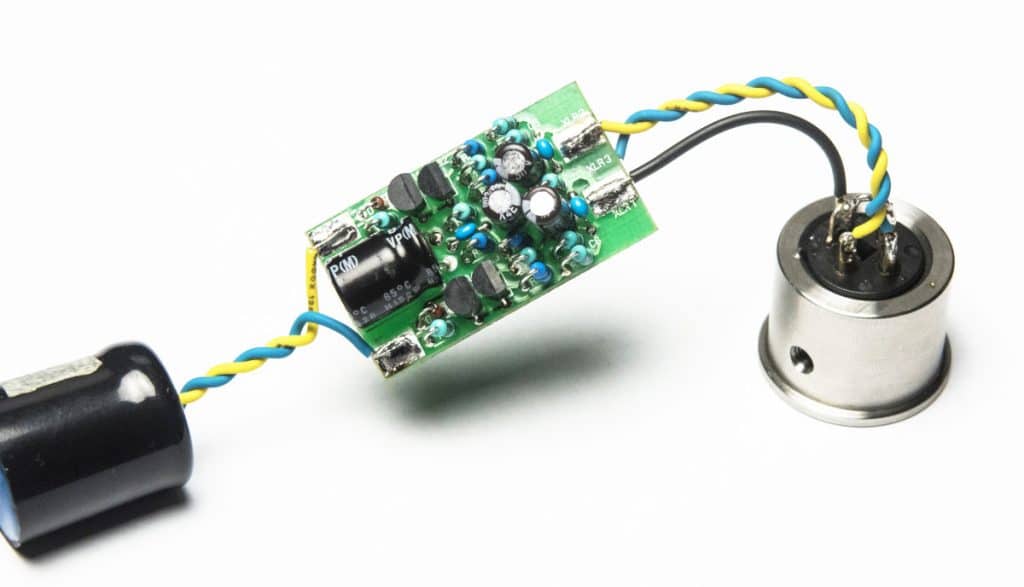
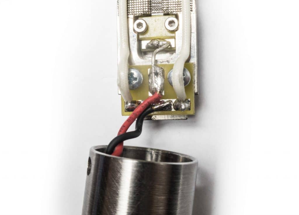
6. Solder The Activator PCB To The XLR Socket
Solder the activator PCB output to the XLR socket of the mic. The yellow wire goes to the XLR Pin 2 and the blue wire goes to the XLR Pin 3. Solder the ground wire from the XLR socket to the “XLR1” pad on the activator PCB. Use the same technique with a female XLR plug when soldering the wires on the XLR socket.
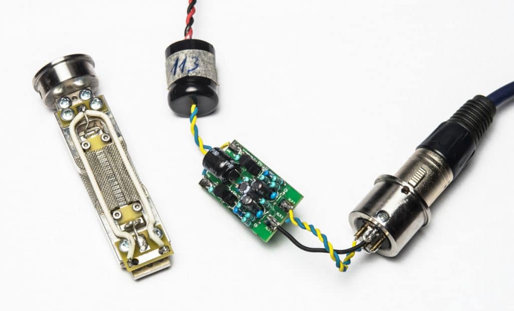
7. Prepare All The Parts In Order To Test The Activator
Now you are ready for testing. Get the motor you’ve prepared in the beginning and the XLR-PCB-transformer assembly you’ve just soldered together. Put the headphones on and get ready for the magical moment of the first sound…
Attention: switch the Phantom Power ON!
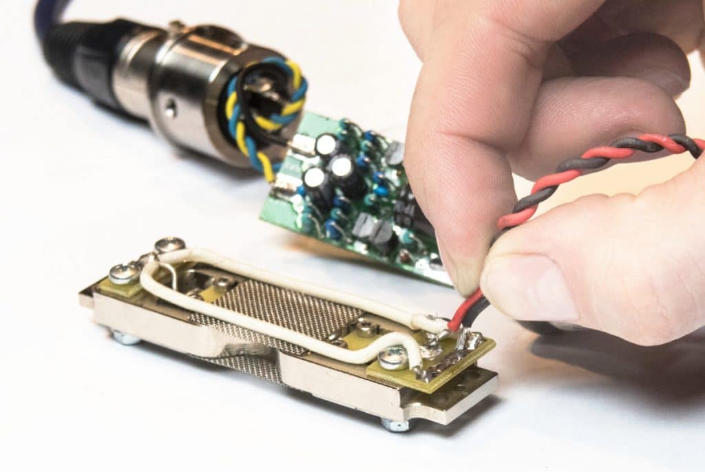
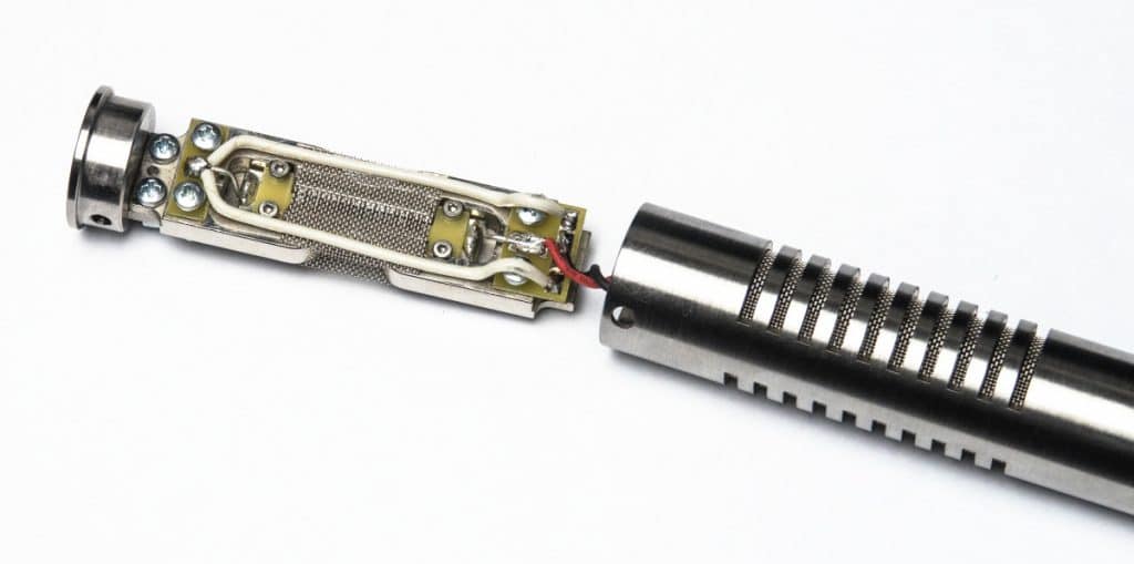
8. Test The Whole Ribbon Mic System Outside The Body
Take red and black wires from the transformer output and touch the contact pads on the motor. The order does not matter at this step, but normally you should have the red wire on the central pad and the black wire on the long bottom pad. See the picture below. Now make some noise.
Any sort of sound in your headphones would mean that the test is passed. The quality of the sound does not matter, as the motor cannot sound properly when laying flat on a surface. Moreover, you may hear the noises and interference sounds – it is normal, as you have the wires in your fingers and the whole system is not screened with a metal body.
9. Wrap The Activator PCB With an Electrical Tape
Wrap the activator with any type of electrical tape. The thinner tape is preferred. Normally the system should work even without the insulation, but I prefer to stay on the safe side and always use the tape. Do not overwrap as then you will have problems pushing the PCB into the body.
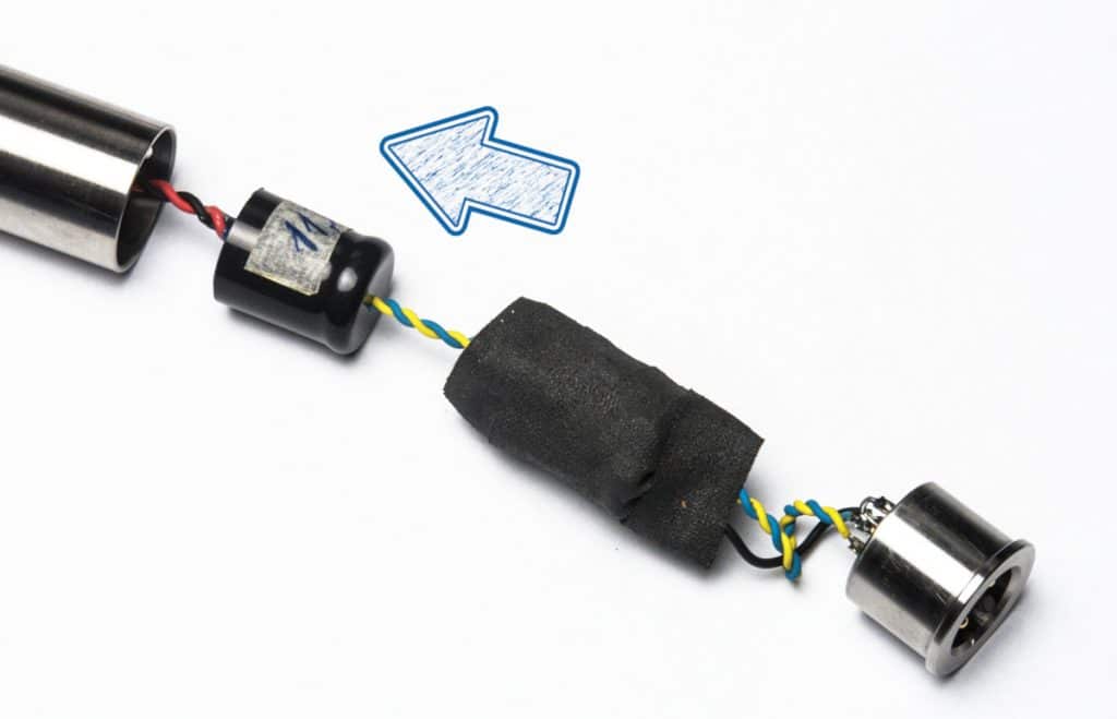
10. Insert The Transformer and The Activator PCB Into The Mic Body
As simple as written above – insert the transformer and the activator PCB into the body from the bottom side. The PCB fits a little tightly when wrapper in a tape. It is normal use some minor force to push it in. Push it as far as it goes. Then rotate the bottom cap a couple of times in order to coil the wires.
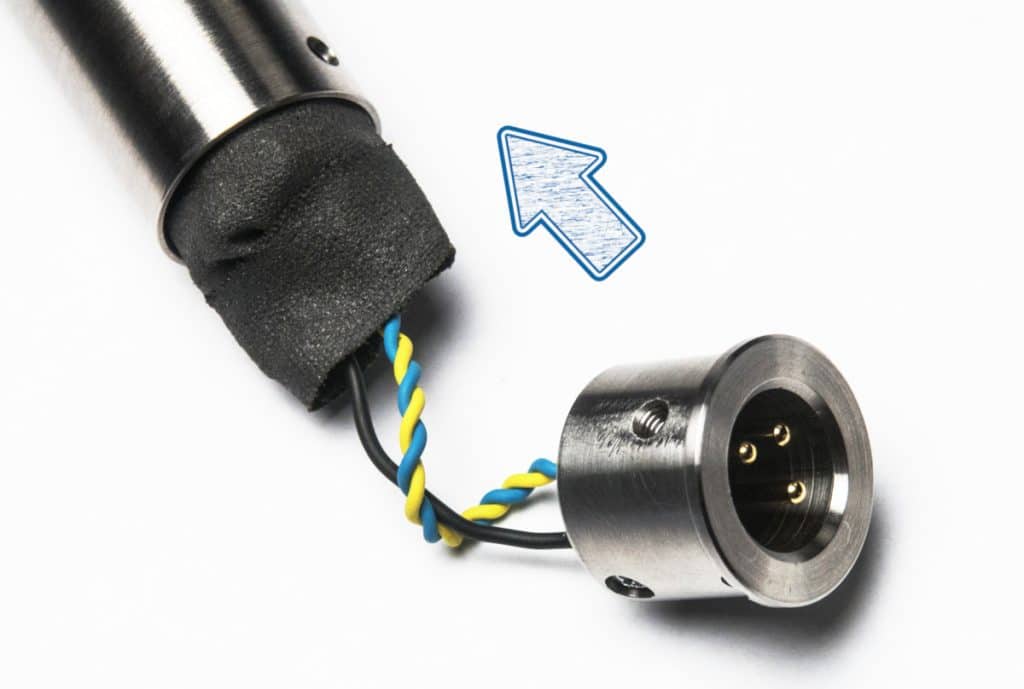
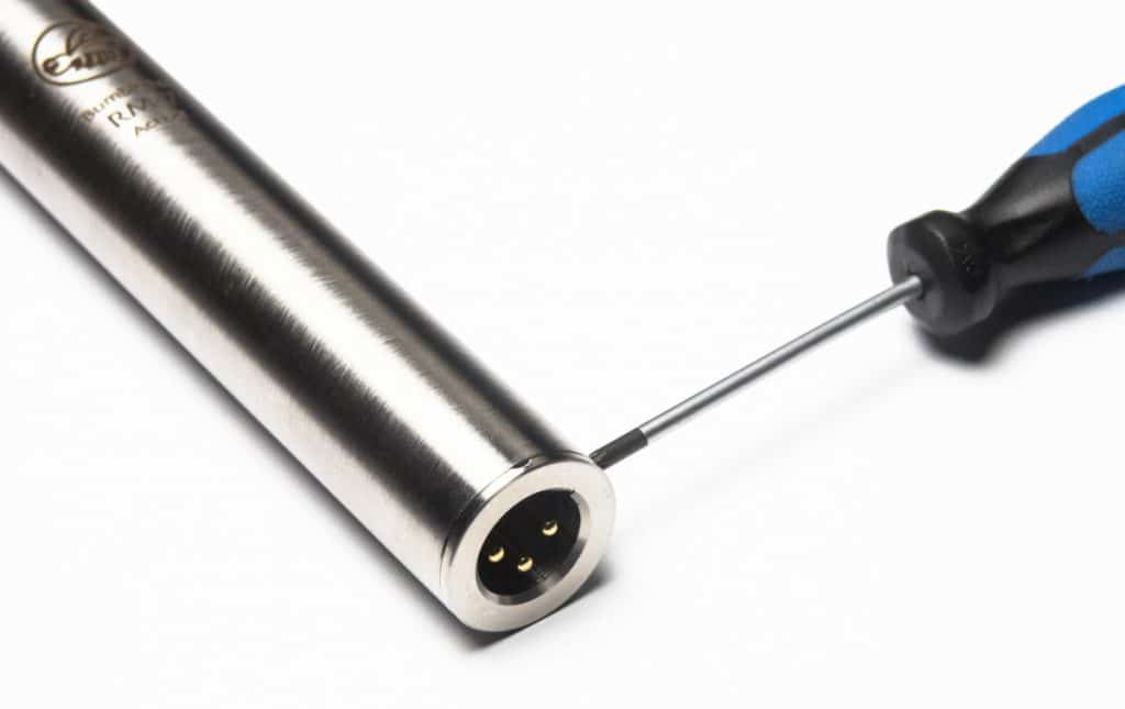
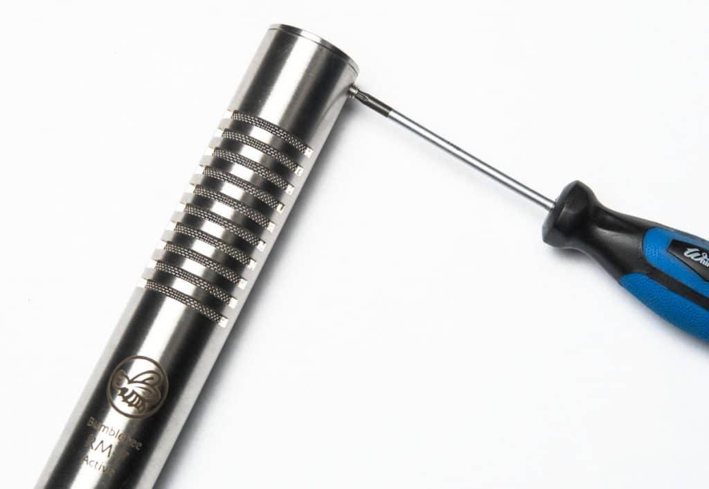
11. Close The Bottom Cap and Fix it With a Screw
When the bottom cap is in, use the supplied screw to fix it in place. In case if the bottom cap is not perfectly tight and wobbles a little, take it out and add a small piece of a scotch tape to the side of the bottom cap. Then close and fix the bottom cap again.
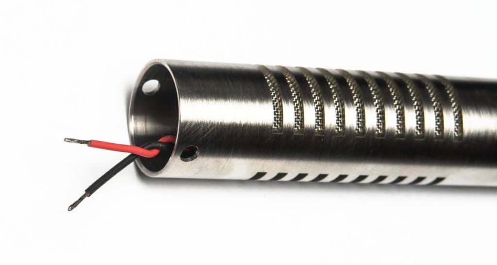
12. Pull The Transformer Wires Out Of The Mic Body
Get the red and black wires out of the top of the microphone if they are not already out.
13. Solder The Transformer Wires To The Motor
Solder the wires to the motor. The red wire goes to the central pad and the black wire goes to the long bottom pad. See the pictures below.
Warning: do not blow on solder points in order to cool them, as blowing can damage the ribbon!
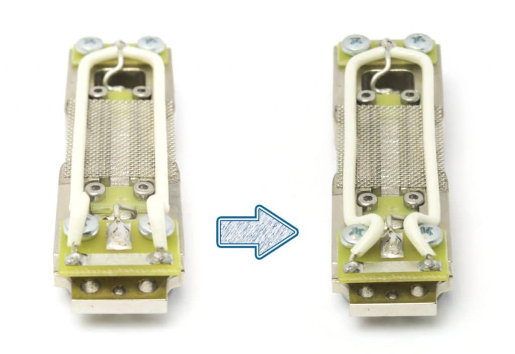
14. Bend The Wires Down
Bend the the wires over the bottom PCB plate down as show on the picture below. Otherwise it will be difficult to insert the motor into the body.
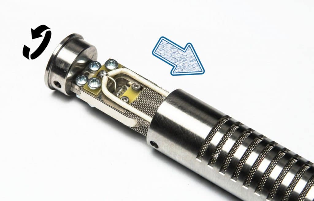
15. Insert The Motor Into The Microphone Body
When the wires are soldered, use a long dull object (like a back of a pencil) and push the transformer slightly deeper, as far as it goes without forcing. Then insert the motor into the body. While pushing the motor in rotate it in the same direction as the wire twisting, e.g. by rotating the motor the wire twisting should get tighter and the wires will start coiling – that’s exactly what you need to pack the wires tightly between the motor and the transformer. In the end the front of the motor (where the screw heads and white wires are located) must be aligned with the logo side of the body.
16. Close The Top Cap and Fix it With Screws
When the cap is full in, use two supplied screws to fix it in place. That’s it, you can connect the microphone and rock-n-roll!