
[vc_row][vc_column offset=”vc_col-lg-offset-2 vc_col-lg-8″ css=”.vc_custom_1544704227948{padding-top: 50px !important;padding-bottom: 80px !important;}”][vc_column_text]
Bb-P26 Ribbon Mic Booster DIY Kit Assembly Manual
Illustrated step-by-step guide to the assembly process of Bb-P26 Ribbon Mic Booster DIY Kit.
Published: 2018.12.12, last updated: 2019.01.18. Author: Artur Fisher.
Few Introductory Words
Dear DIY fellows! This project took quite long to develop, as I wanted to share the best possible quality with you. It is a simple DIY build, however, the circuit design was very complicated. The booster features ultra low-noise NOS transistors and the whole circuit is internally balanced. The device does not need any calibration and will function perfectly right after assembly.
I am sure you will find lots of uses for this Mic Booster in your everyday studio works.
Cheers!
Yours sincerely,
Artur Fisher.
1. What’s In The Box
You will receive all the required parts:
- All the electronic components – resistors, capacitors, diodes
- A pair of ultra low-noise NOS transistors
- BC547C bipolar transistors
- Neutrik input and output XLR sockets
- PCB (printed circuit board)
- Pre-drilled and punched, powder coated and silkscreened enclosure
- All the required screws
What else is needed:
- Soldering iron with fine tip
- Some solder wire, preferably 0.5 mm thick
- Digital multimeter for sorting the resistors
- 5/64 Hex Wrench (Allen Key) or screwdriver with 5/64 hex head
- Philips screwdriver
- Some type of wire cutters to clip the component leads
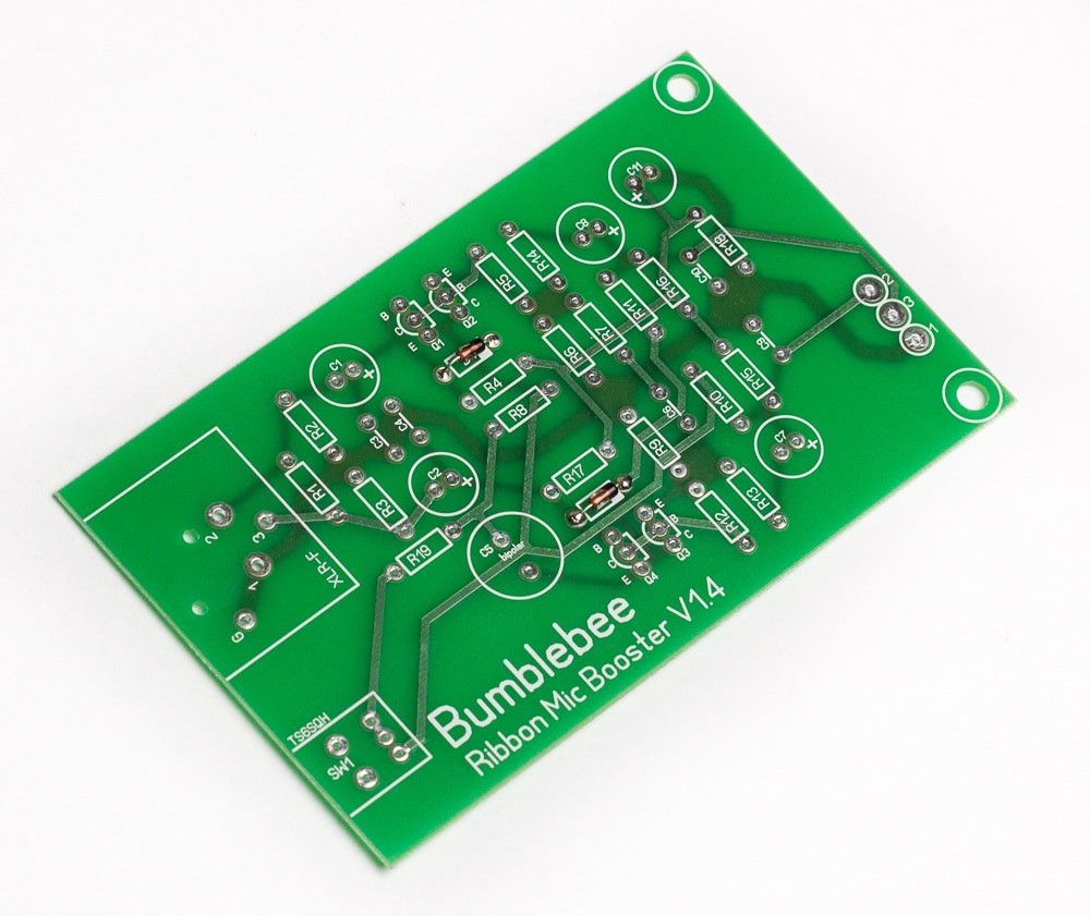
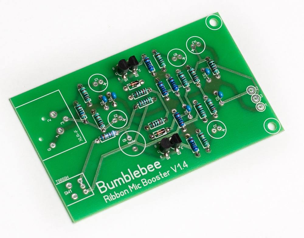
2. Solder the diodes on the PCB
Let’s begin with assembling the PCB. I always advice to solder the smallest components first and proceed to bigger ones with each step. There are two pcs of 1N4148 diodes in the kit. Place them on their spots marked as D1 and D2. Note that the diodes are polarized! The black band on the diode must align with the white band on PCB marking. Diodes are heat sensitive! So the best practice is to solder one lead of each diode first and then proceed to the second lead of each diode, this way you will give them some extra time to cool down.
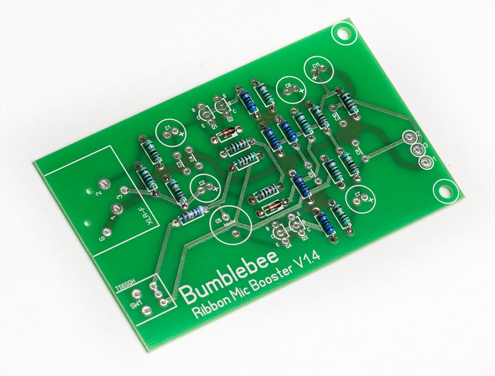
3. Solder the resistors on the PCB
This part usually takes the most of the time, as you have to measure all the values. So, get the multimeter, take a random resistor out of the bunch and measure its value. Then find the value in the list below and see where it goes on PCB. Insert it and proceed with the next one until you have all the resistors in their places. Resistors are not polarized, so don’t stress about their orientation.
- 51Ω: 2 pcs, R13 and R14
- 56Ω: 1 pc, R19 this resistor sets the high gain
- 510Ω: 1 pc, R8 this resistor sets the low gain
- 680Ω: 3 pcs, R5, R7 and R12
- 1KΩ: 2 pcs, R6 and R9
- 6.8KΩ: 1 pc, R1 this resistor sets the input impedance
- 10KΩ: 3 pcs, R4, R17 and R18
- 18KΩ: 2 pc, R10 and R11
- 120KΩ: 4 pcs, R2, R3, R15 and R16
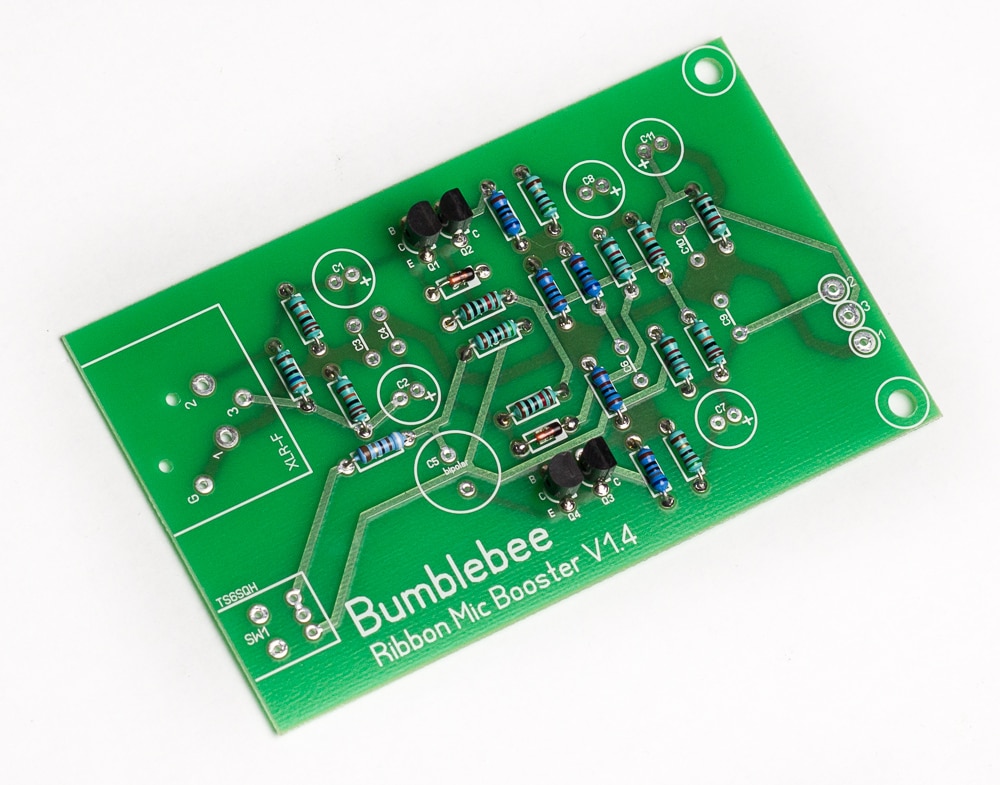
4. Solder the transistors on the PCB
There are two types of bipolar transistors in this direct box circuit – BC547C (NPN) and 2SA970BL (PNP). The part type is printed on the flat side of transistor body.
- 2SA970BL: 2 pcs, Q1 and Q4, for ultra low-noise input
- BC547C: 2 pcs, Q2 and Q3
Place the transistors on their spots. The rounded side of a transistor must align with the rounded part on PCB marking. Again, solder one lead of each transistor at a time. Transistors are heat-sensitive, so solder them quickly.
5. Solder the ceramic capacitors on the PCB
There are five ceramic capacitors (small blue ones). These are very high quality audio friendly C0G/NP0 units. These capacitors are not polarized, so the orientation is not essential. Please note that you might need a magnifying glass to see the values printed on the components, as there is a very fine print.
- 100pF: 3 pcs, C3, C4 and C6
- 680pF: 2 pcs, C9 and C10
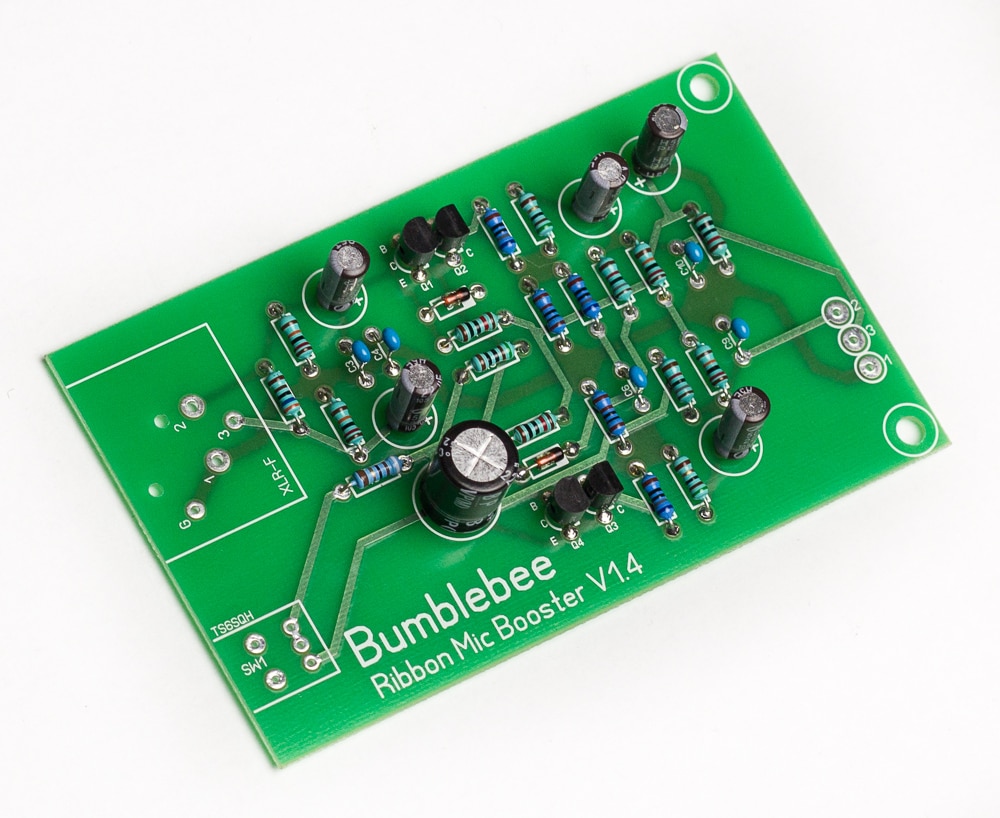
6. Solder the electrolytic capacitors on the PCB
There are six electrolytic capacitors in the kit. Five of them are polarized, which means that they must be properly oriented. Plus sides are marked on the PCB. One of the capacitors (C5) is a bipolar electrolytic and is not polarized, so the orientation is not essential.
- 22uF/50V: 5 pcs, C1, C2, C7, C8 and C11. These capacitors are polarized
- 220uF/16V: 1 pc, C5. This capacitor is not polarized
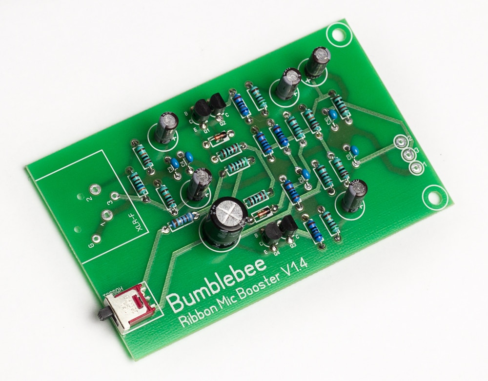
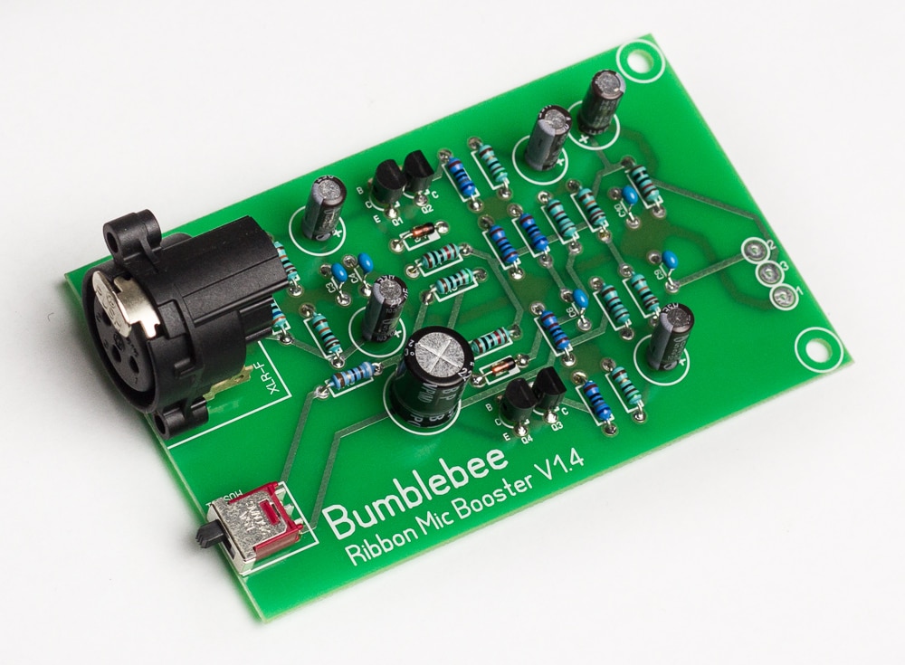
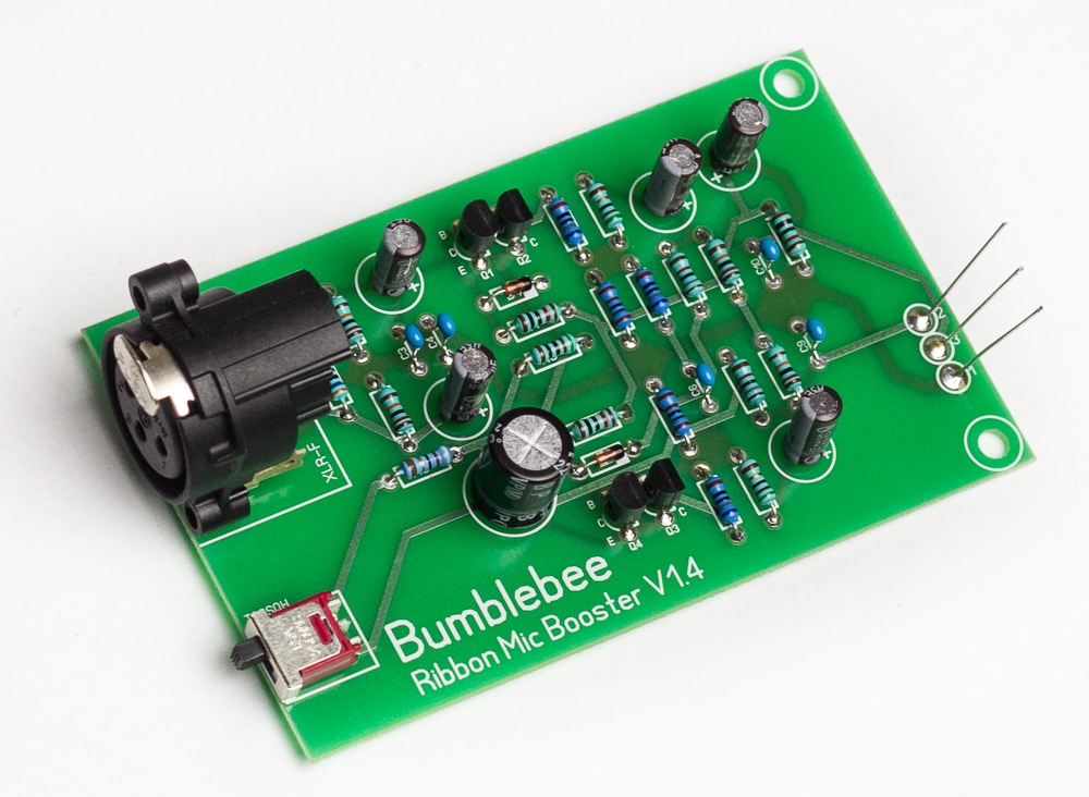
7. Solder the switch, female XLR and jumper leads on the PCB
This part is easy, as there is no room for the possible mistake. Just solder the switch (selects high or low gain modes), female XLR (mic input) and jumper leads (use the remains of resistor leads) for connection to male XLR (output). See the photos below.
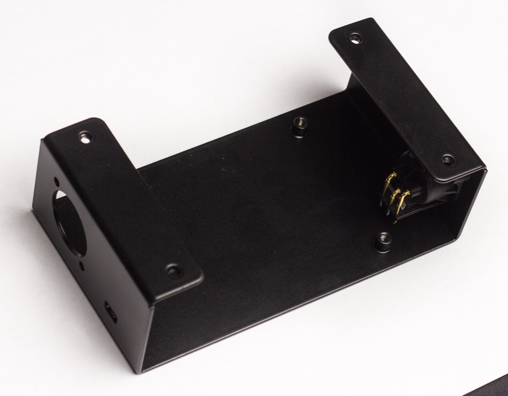
8. Fix the male XLR in the enclosure
Use two of the supplied self-tapping screws to fix the male XLR in the enclosure as shown on the photo below. Please note the standard rule of thumb for using self-tapping screws: when you screw them in go half-turn forward and quarter-turn out. It will prevent the plastic from breaking.
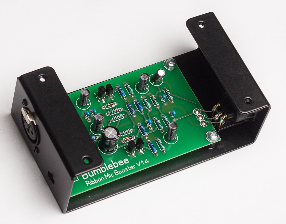
9. Fix the PCB in the enclosure and connect to the male XLR
Insert the pcb in the enclosure. First, use the M3 screws to hold the PCB in place, but don’t fasten them yet. Use the supplied metal washers above the PCB and 2mm plastic spacers below the PCB. Next, use another pair of self-tapping screws to fix the female XLR. Finally, you can tighten the M3 screws.
When the PCB is fixed in place, solder three jumper leads to the corresponding pins of the male XLR. See the photo below. The most convenient practice is to start from the middle one. Important note: plug in the female XLR plug into the socket before soldering. It will work as a heat sink and prevent the pins from displacing in case you overheat them.
Test the device at this point to make sure everything is done correctly. Plug in the microphone, connect the Bb-P26 booster to the preamp with +48V phantom power, switch the phantom power on and check the sound. Congrats!!
10. Fix the top of the enclosure
Cover the assembly with the top part of the enclosure and use the black M3 screws to fix it. You’ve made it!! Enjoy the new sound of your ribbon and dynamic microphones!

[/vc_column_text][/vc_column][/vc_row]