Bb-A20 Ribbon Mic Activator - Assembly Manual

Illustrated step-by-step guide to the assebly process of the Bb-A20 Ribbon Mic Activator DIY kit.

Published: 2019.10.16, last updated: 2019.10.16, author: Artur Fisher.

Bb-A20 DIY Ribbon Mic Activator Kit

What's In The Box

  • PCB
  • Full set of components – resistors, diodes, capacitors, transistors

What else is required:

  • Soldering iron with a fine tip
  • Some solder and flux
  • Multimeter to sort the resistors
  • Magnifying glass might be needed

1. Solder The Ceramic Capacitors

Solder three C0G/NP0 ceramic capacitors on the PCB. Ceramic capacitors are not polarized, so the orientation of the components is not essential. The values are marked on the capacitors with a very fine print, so magnifying glass might be needed.

Values:

  • 100 pF: C2
  • 680 pF: C5, C6 (these capacitors can also be 470pF and yellow color)
DIY Ribbon Mic Activator Kit Assembly Manual - Ceramic Capacitors

2. Solder The Diodes

Solder the diodes on the PCB. The diodes are polarized! The black ring on the diode must be aligned with the bold white line on the PCB marking. The diodes must be soldered in “standing” position.

Types:

  • 1N4148: D1, D2
DIY Ribbon Mic Activator Kit Assembly Manual - Diodes

3. Solder The Resistors

Solder the resistors on the PCB. The resistors are not polarized, so the component orientation is not essential. Use the multimeter to check the resistor values. Resistor numbers starting with “10” are marked without the “R” prefix on PCB in order to save the space. The resistors must be soldered in “standing” position.

Values:

  • 51R: R10, R11
  • 100R: R4
  • 680R: R2, R5, R9
  • 1K: R3, R8
  • 10K: R1, R14, R15
  • 18K: R6, R7
  • 120K: R12, R13
DIY Ribbon Mic Activator Kit Assembly Manual - Resistors

4. Solder The Transistors

Solder the transistors on the PCB. The transistors must be oriented the same way as marked on the PCB – the rounded side of a component must align with the rounded side of marking. The transistors are heat sensitive! Be sure not to overheat them while soldering. The best practice is to solder one leg on each transistor first, then the second leg of each transistor, etc. This way the transistors will have more time to cool down.

Types:

  • 2SA970BL: Q1, Q4
  • BC547C: Q2, Q3

5. Solder The Electrolytic Capacitors

Solder the electrolytic capacitors on the PCB. The 22uF capacitors are polarized! The “minus” side is marked on the capacitor body, the “plus” side is marked on the PCB. The 220uF capacitor is bipolar, e.g. it is not polarized and can be installed in any orientation.

Values:

  • 22uF: C3, C4, C7
  • 220uF: C1 (non-polarized)

6. Wiring The Bb-A20 Mic Activator

The wiring of the Bb-A20 Ribbon Mic Activator is very simple and straight-forward. 

Soldering points:

  • POS: the “positive”/”hot” output lead of a ribbon mic transformer
  • NEG: the “negative”/”cold” output lead of a ribbon mic transformer
  • XLR1: to the output XLR pin 1 (ground)
  • XLR2: to the output XLR pin 2 (“hot”)
  • XLR3: to the output XLR pin 3 (“cold”), located on the back side of the PCB

Don’t be afraid to mix up the “positive” and “negative” wires of the transformer, everything will work, just with the reversed phase, e.g. the back of the microphone will become its front. It can be easily corrected by swapping the wires on the output XLR socket pins 2 and 3.

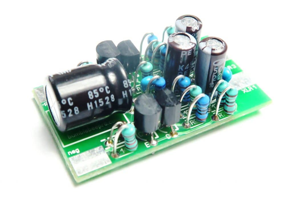
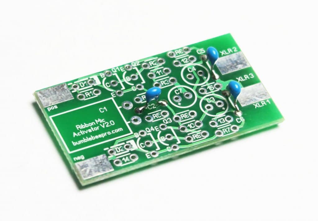
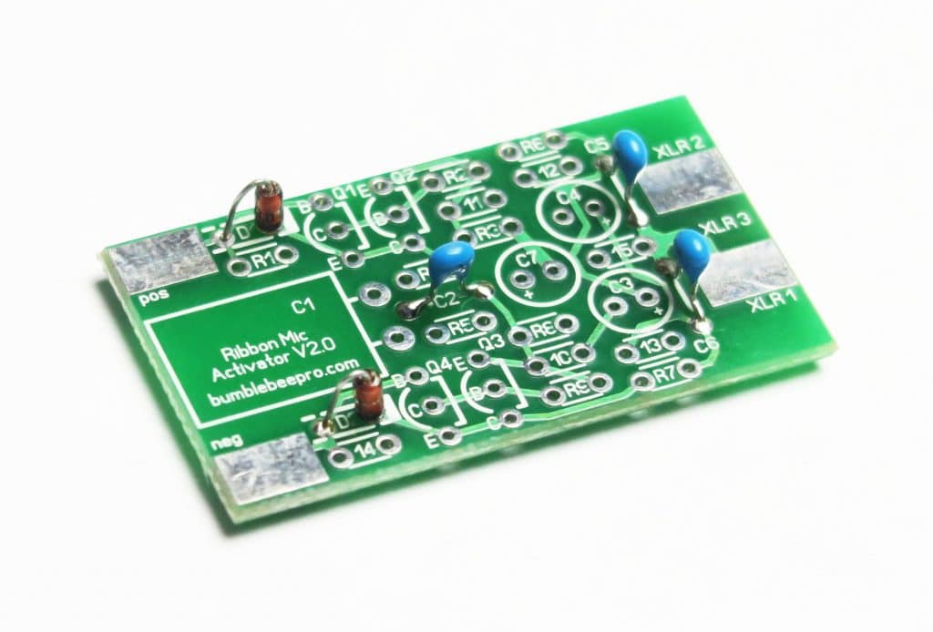
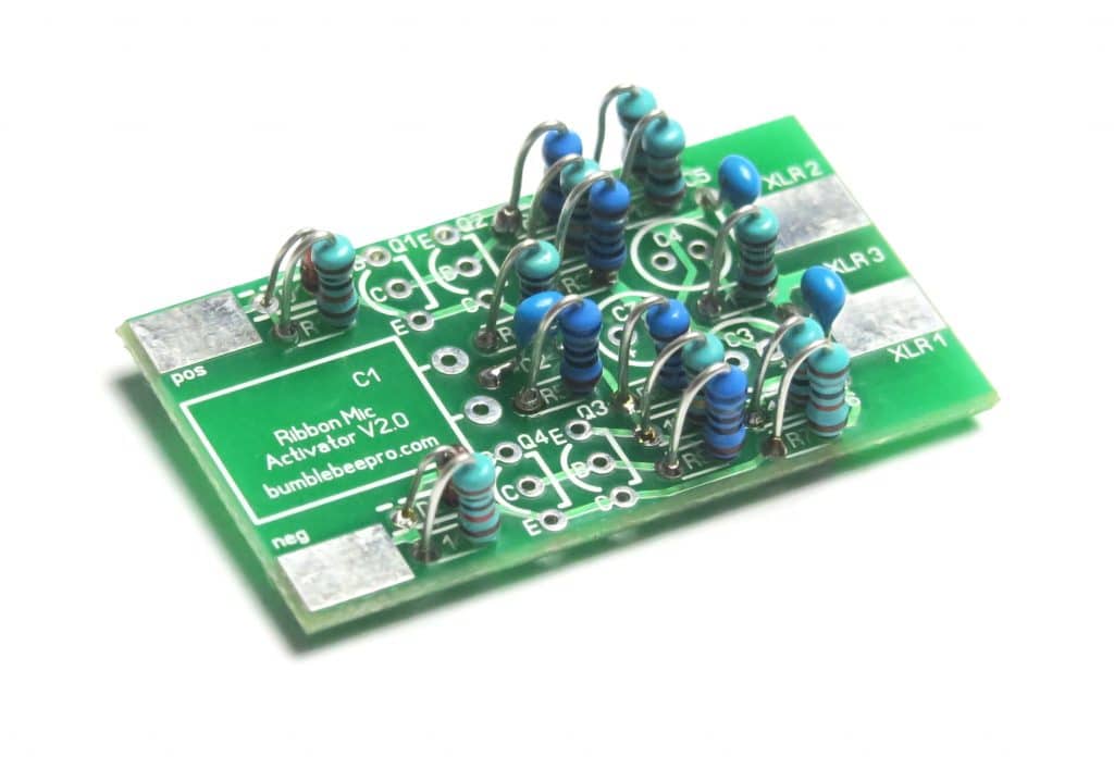
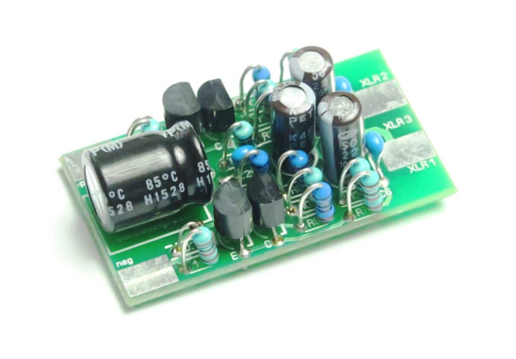
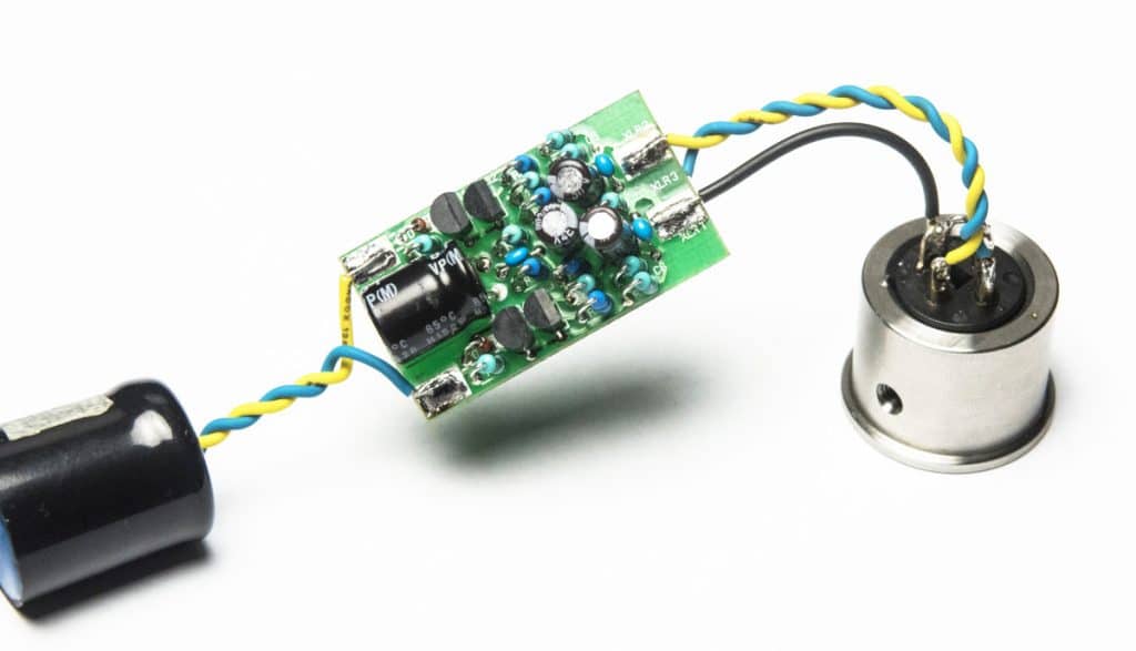
If you are upgrading the stock passive ribbon microphone then follow such procedure: simply re-solder the wire from XLR pin 2 to POS pad on the PCB and the wire from XLR pin 3 to NEG pad on the PCB, then connect the “XLR” marked pads on the PCB to the corresponding pins on the output XLR socket.