
DIY Ribbon Microphone - Ribbon Techniques
Aluminum Foil Gauges
Ribbon is made of a strip of an ultra-thin aluminum foil. As thinner is foil, as higher output signal level You will have, as signal level is reverse proportional to the mass of a ribbon, but there are logical limitations. First, foils of 1.5 microns and below are very difficult to handle. Second, even if You try hard enough and manage to make a motor with such thin ribbon, the microphone is going to be extremely fragile, as even lightest pop or impact can blow the ribbon away, so You might end up in becoming paranoid about the possible abuse during sessions.
On the other hand, foils of 4 microns and above are not a good idea, because ribbon mass is going to be too high for a good performance. The problem is not only in output signal level. The main issue with heavy ribbons is that they are tend to compromise the main feature that ribbon microphones have – a nearly perfect transient response. Ribbon microphones have many cons by their nature, so designing a ribbon microphone without the main advantages makes no sense. By the way, many of cheap ribbon microphones have ribbons made of up to 6 micron thick foil… In general, the best gauges to use are between 2.0 and 3.0 microns. The most most widespread option for ribbons is 2.5 micron thick foil, as it not that difficult to handle and it performs very well in motor assemblies. I offer 5.0″ x 2.5″ sheets of 2.5u Al foil for purchase online.
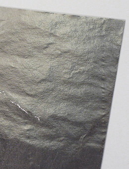
A sheet of 2.5 micron aluminum foil for DIY ribbon microphones
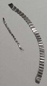
Two DIY microphone ribbons – large and small
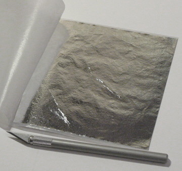
Aluminum foil for ribbon microphones with a cutting tool (a scalpel)
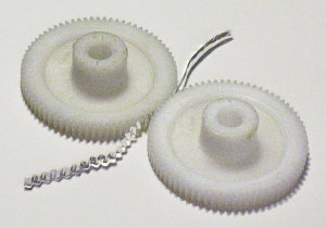
Corrugation of a ribbon using a pair of plastic gears – the simplest method of foil shaping
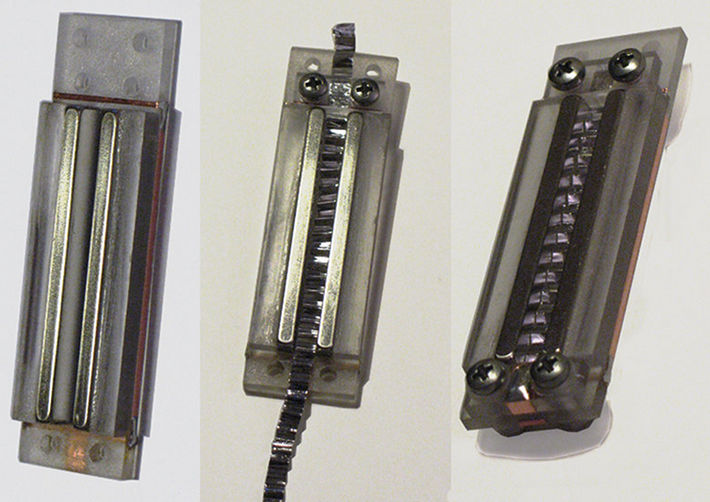
A very simple DIY ribbon microphone motor with a plastic frame
Ribbon Dimensions
After we have chosen the foil gauge, we have to decide on final dimensions of a ribbon. Its lengths is determined by the length of magnets used, so You should decide how long Your ribbon is going to be to choose and purchase appropriate magnets. The most typical ribbon lengths are between 1″ and 2″. Of course, there are designs with longer and shorter ribbons, either, but it is good starting range to choose from. I would advice to go for a ribbon between 1 1/2″ and 2″ in Your first design. Through it is logical that length adds to the mass, it factually does not affect the signal level much, as when You increase the length of a ribbon, the length of magnets increases same way, providing proportionally stronger magnetic field.
What really does affect the relation of ribbon mass to magnet strength is the width of a ribbon. Ribbon widths can vary within 2 mm – 6 mm (0.04″ – 0.25″), so the range to choose from is pretty wide. Again, when You half the width, the signal output level doubles. I have designed motors with down to 1.5 mm (0.06″) wide ribbons and I can tell You, that working with such narrow ribbons takes huge effort, so I would advice something in a range of 4 mm – 6 mm (0.16″ – 0.25″) for Your first motor. The width of a ribbon is physically determined by the gap You leave between magnets in Your assembly, so You should decide on desired width when designing chassis.
Corrugations and Ribbon Tension
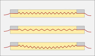
1. Correct tension
2. Overtensioned ribbon
3. Undertensioned ribbon
The whole logical chain again: the tension determines the resonant frequency, but the possible tension range is determined by elasticity – as higher is the elasticity, as lower possible tension we can apply, while elasticity itself is determined by the corrugation style.
When we talk about corrugation style we mostly assume the corrugation density, e.g. the amount of foil deviations per a certain length, usually measured in corrugations per inch.
The most widespread density is around 20 – 24 corrugations per inch. I have tried different densities and can confirm, that this range can be considered optimal for 1 1/2″ – 2″ long ribbons. I have observed, that increasing the corrugation density usually tends to add more tension to a ribbon, thus raising the resonant frequency. On the other hand, decreasing the density can compromise the stability of the form – the displacement of ribbon angles from the central axis gets to high and ribbon tends to lose the form under its own weight. In general, for the optimal balance between the elasticity and tension, the angles of foil strip deviations should be around 90 degrees (when fixed on chassis).
Fixing a Ribbon On a Motor
Now the ultimate part. Ribboning. In general, there is not much to talk about, it is mostly about “feeling” the way, it can only be understood when done, so put Your patience together and get ready to try. First, place the ribbon in a gap and make sure that it can be settled comfortably. Then put the first clamp on, screw nuts on bolts (until they are all the way down, but not fixed) and use the outer tail to position the ribbon in a gap the best possible way (to have an equal space between the ribbon and the magnets on both sides). Now lightly fix nuts. You have one side pre-fixed, but be careful, You still can displace the ribbon if You make a wrong move.
Get to other side and repeat everything as with the first clamp, but this time You have to set the tension together with position. Gently and slowly drag the ribbon outside watching it to keep good positioning in a gap. The correct tension is just when it doesn’t bend down under its weight anymore. Just when it stays horizontal, not tighter! Speak or sing over the motor (I keep about 5″ distance) and watch the ribbon moving. It should move freely all along the gap. If it touches the magnet (You can see it by uneven motion), correct the positioning. If it bends down again after You spoke, apply a little bit more tension. Repeat the procedure until the ribbon returns to clearly horizontal position after visible vibration. Fix the screws. Now recheck the position of ribbon in a gap all over its length, You might want to undo nuts lightly and to correct the position of ribbon on either side, but do it very gently and fix the nuts again. Now apply a little bit more tension to nuts. Note, that You should not use a screwdriver until the very end – tighten and untighten the screws with fingers. Check the appearance of ribbon again, try to speak, when the motor is in vertical position, rotate it, try different angles and watch the ribbon. In general, it should keep its form now. Apply all the tension to screws You can with bare fingers.
Now it’s time for a multimeter. Set it in continuity testing mode and touch both contacts on a motor (corresponding to opposite sides of the ribbon) with probes, but be sure not to hold, as it can be bad for a ribbon, just touch for a short beep and release. The ribbon should bend about half-way up or down when probes are applied and restore its position when probes are off. Now set the multimeter in resistance testing mode (in its lowest range) and check the value. In the best case, multimeter should read something in the range of 0.7 – 1.1 Ohms, but it can be higher now because pressure between the ribbon and contacts is not strong enough. Now set the multimeter in continuity testing mode again and check for the contacts between ribbon and either of magnets. It should be perfect zero. Check and recheck. If everything is fine, take the screwdriver and tighten the screws again, but don’t apply force. I usually do just about half-turn more on each screw. If resistance reading was too high, check it again, it should be fine now. Well, if it is a bit more then it is supposed to be, like, 1.5 Ohms, try applying a little more tension to screws, but really, just a little more. Anyway, static resistance up to 1.5 Ohms is OK.
Voila! You made it! Connect the motor to transformer, plug into a preamp and enjoy. Again, it can’t be stressed much enough – always remember to use the pop-filter, it is very easy to blow or stretch the ribbon with occasional pop. Have great recordings!