
DIY Ribbon Microphone - Magnets
The required materials to make a ribbon motor are permanent magnets, thin aluminum foil and something to craft the chassis of. We will begin from probably the most confusing component – the magnets. Of course, I could just tell you the exact models of magnets, but I have written these materials in order to provide a deeper understanding of the matter for you could think, decide and design Yourself. That’s what DIY is about.
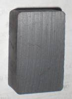
Old-school ceramic magnets that were used for many years.
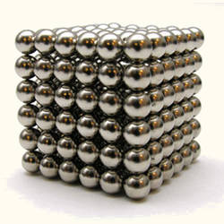
There are four most widespread types of permanent magnets: ceramic (ferrite), AlNiCo (aluminum-nickel-cobalt-iron) and two types, that belong to rare-earth magnet group – SmCo (samarium-cobalt) and NeFeB or NIB (neodymium-iron-boron). Ceramic and AlNiCo magnets have been in use for long times and classical ribbon microphones were designed using these types. Rare-earth magnets were in development from some 70es and became publicly available in the beginning of 80es. This is an explanation of a huge ribbon microphone revival that begun in 90es, as new magnets were incredibly strong comparing to older types and allowed to design ribbon microphones with up-to-date characteristics.
There are various specs in description of magnetic properties of materials, but the one that is the most important for us is BHmax, measured in MGOes (megagauss-oersteds). I will not try to explain in details what it means, but in simple words BHmax defines the amount of energy the magnet can supply in relation to the volume of magnetic material. Consider it the “power” of magnet divided by its volume. Consequently, if we have few magnets of the same volume with different BHmax values, the one with the highest BHmax value will generate the strongest magnetic field.

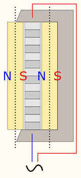
The arrangement of magnets in a ribbon microphone motor. Note that the magnets are fixed in the attraction position
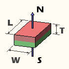
The magnetization direction “through thickness”
Classically, magnetization direction of block magnets was referred as “through width”, “through length” and “through thickness”. The dimensions are described in following order: length x width x thickness. Imagine it, like if some virtual surface would perpendicularly pierce through (that’s why this word is used) the selected dimension. In this case, poles would be located on surfaces that are parallel to this virtual surface. Some manufacturers define it this way, but some just define the factual dimension a magnet is magnetized through as “thickness”. Some just provide dimensions, like 2.0″ x 1/4″ x 1/8″, and note the dimension a magnet is magnetized through, like “magnetized through 1/8”. Magnets are usually magnetized through the smallest dimension for poles to be located on largest surfaces. For ribbon microphone applications we need both magnets to face the ribbon with surfaces that carry the opposite poles, so the magnetization direction with poles on largest surfaces is exactly what we need.
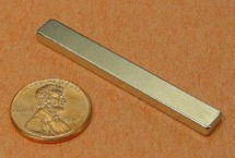
2″ x 1/4″ x 1/8″ NdFeB magnet
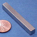
2″ x 1/4″ x 1/4″ NdFeB magnet
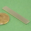
1 1/2″ x 1/4″ x 1/16″ NdFeB magnet
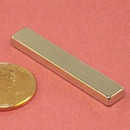
1 1/2″ x 1/4″ x 1/8″ NdFeB magnet
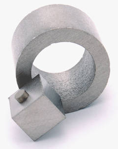
As I’ve mentioned, the most useful shape for DIY designs is block. Some other options, like horseshoe shaped magnets, can be applied too, but these are going to be a bit more advanced designs. I have even seen some exotic designs that used disk or cylinder magnets, but we will concentrate on the most straightforward solution further on – a block. The most useful lengths are between 1″ and 2″, magnets are usually manufactured with lengths increasing in 1/4″ steps. Width is usually taken as 1/4″, it determines the depth of the gap and thickness of your motor (do not confuse with the thickness of a magnet itself!). Thickness of magnet can be between 1/16″ and 1/4″, it adds to the width of Your motor. Of course, these numbers are not ultimate and you are free to experiment with any sizes, these are just good starting points. The length of magnets is normally the first dimension to choose, as it determines the approximate length of a ribbon you will have to use.