
RM-5 / RM-6 Ribbon Microphone Kit Assembly Manual
Illustrated step-by-step guide to the assembly of RM-5 and RM-6 ribbon microphone DIY kits.
Published: 2014.07.15, last updated: 2017.02.26. Author: Artur Fisher.

Foreword
Dear DIY audio fellows, this manual describes and illustrates the whole assembly process of the Ribbon Microphone Kit with detailed description of each step, tips and warnings where necessary. The assembly processes are almost identical for RM-5 and RM-6 kits, so the description is based on the original RM-5 Kit manual with extra pictures and notes regarding RM-6 Kit where required. I hope you will enjoy building this great microphone as well as using it in your everyday sessions.
I did my best to make sure that this manual is clear and each step is easy to understand, however, if something still feels confusing for you, please send me an e-mail: info@diyaudiocomponents.com. I will address your issue ASAP and will provide the necessary assistance.
Cheers!
Yours sincerely, Artur Fisher.
1. What is in the box
What’s in the box:
- Full microphone body, including grill and output XLR insert
- Cardboard storage box for assembled microphone
- RE-254 Ribbon Motor, comes assembled (RE-323 Ribbon Motor with RM-6 kit)
- RTX-35 Toroidal Output Transformer (RTX-28 Transformer with RM-6 Kit)
What else is required:
- Soldering iron
- Some solder
- 5/64 Hex Wrench (Allen Key) or screwdriver with 5/64 hex head.
- A small piece of wire for a jumper
- A tiny piece of scotch tape might be needed
RM-5 Kit:

RM-6 Kit:

2. Solder the jumper
Solder a jumper between XLR Pin-1 and Ground Pin (as on picture below). You can use a small piece of wire or an unneeded component lead for this purpose. The jumper connects the cable screen to the body of the microphone. It is required, so the body would act as an EMI shield.

3. Prepare the output transformer
Strip and tin the ends of transformer leads, twist the lead pairs – Black with Red and Yellow with Blue.
Warning: hold the roots of a wire pair securely with one hand when starting twisting to prevent the possible lead damage. Please also note that proper lead twisting may be critical for EMI immunity. Lead pairs must be twisted tightly and evenly, as on picture below.

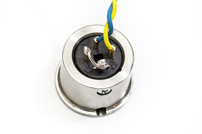
4. Solder the transformer output leads to XLR
Solder the output leads (Yellow and Blue) to the XLR Pin-2 and Pin-3. Yellow wire to Pin-2, Blue wire to Pin-3. Pin numbers are marked on the XLR insert near soldering terminals, or use a picture below as a guide.
Warning: when you are soldering a male XLR, always plug in the female XLR connector! It will work as a heat-sink and a stabilizer for XLR pins in case if plastic starts melting.

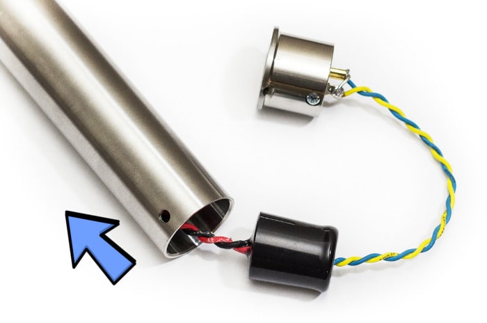
5. Insert the transformer into the body
Insert the transformer into the body from the bottom side. This step requires some care, as transformer is made to fit tightly in the body. You might need to adjust the position of the transformer and to find the correct angle, so it goes in well. Some small force should be applied, it is normal. Use a long dull object to push the transformer deeper inside until the Yellow and White wires are easily accessible for work from the top side.
Warning: never try to pull the transformer leads in order to move it, you will damage the transformer! The leads are fixed secure enough for normal handling, but they are definitely not made to withstand the mechanical loads!
6. Fix the bottom cap with a screw
Close the bottom cap and use the hex wrench to fasten the screw. Try to move the cap, it might have a little swing. If it does, re-open and add a little piece of scotch tape on the side of the cap. Be sure not to add too much, so the cap would go in without excessive force, otherwise you might have problems opening it later on, if needed.

7. Solder the transformer input leads to the motor
Now, solder the transformer input wires (Red and Black) to the terminals on the bottom pad of the motor. The contact terminals on motor are clearly visible on the pictures below.
Warning: Be sure not to blow on solder points after removing the soldering iron!! It is a very widespread habit and it a good way too cool the point in most cases, but here the directed air flow can easily damage the ribbon! Also, be careful not to make solder bridges between contact terminals while soldering, as they are very close.
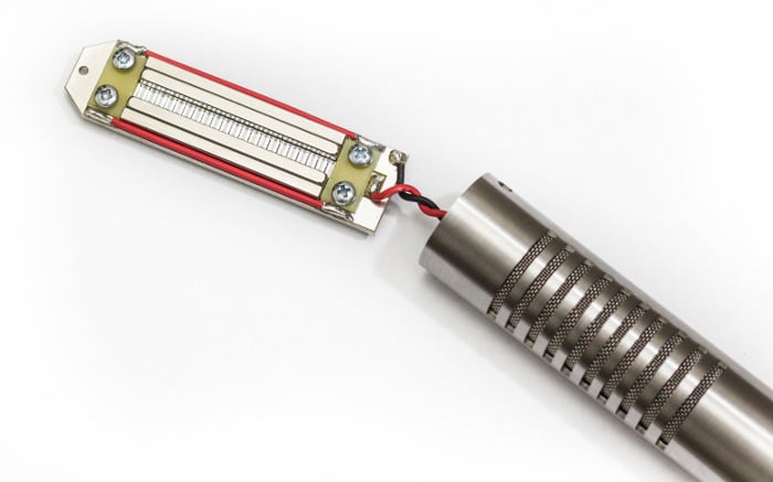
RM-5 Kit RE-254 Motor Soldering

RM-6 Kit RE-323 Motor Soldering

8. Fix the top cap on the motor
Put the top cap on the motor and use the wrench to fasten the tightening screw. The small hole on the top of the motor is made to accept the tip of the screw for correct alignment.

9. Push the transformer deeper into the body
Now, important step to do – use a long dull object to push the transformer back inside towards the bottom side of the microphone. A spoon with a plastic handle is used on picture as an example. I am sure you can find a household object that will be suitable for the job. Your goal is to push the trafo as deep as you are able to in order to keep it further away from motor, when it is inside the body. Permanent magnetic field from motor magnets can influence the performance of the transformer if it is too close.

10. Insert the motor and close the cap
Before trying to push the motor inside, rotate it few times in the same direction as you twisted the wires. It will add some tension to the wires and they will form coils inside the body, making it much easier to force the motor inside. Keep rotating the motor if it feels a little stuck on the way. Usually the total of 4 – 5 full turns is enough.

11. Fix the top cap with screws
Close the cap. Watch to orientate it correctly, as fixing screws are off-center, you might need to turn the cap around, so the screw receptacles would align with the openings on the body. Usually there is no need to add tape to the upper cap, it should stay in place firmly.

12. Enjoy recording your music!!
Well, that’s it! Your microphone is assembled and ready to use! Connect it to your audio interface or console and rock!
Don’t forget to read a little further, there is an important information below on correct phasing (determining the “front” and “back” of the microphone) and explanation of the phantom power related aspects.

RM-5 Ribbon Microphone and Phantom power
Please read a Ribbon Mic and Phantom Power article.
Determining the Front of the Microphone
The motors do sometimes have different phasing, so the best idea would be to make sure where is the in-phase (front) side of your particular unit and mark it.
It is very simple to do: connect the microphone and put the headphones on, then speak into one side, turn the microphone around and speak into the opposite side, you will hear that two sides sound distinctly different in such setup. Do so few times. One side will sound full and bold, while the other side will have lack of bass and overall weird, dull and nasal sound. The side that sounds clear is the front, mark it and use the microphone accordingly.
A little explanation: both sides of the microphone do actually sound the same! If you ask somebody to speak into the microphone in the studio room the same way, while listening via monitors, you will hardly be able to hear any difference. The difference between sides is only audible with your own voice and only in headphones, it happens due to the fact that when you speak into the out-of-phase side (back), the sound that comes into your ear from outside (from the phones) is out of phase with the sound that comes into you inner ear via bones, these two sources interfere in your inner ear causing the weird sound effect! This effect can be observed with any figure-8 microphone and has a good use in confirming the front side of any ribbon mic when needed.
Thank you! Hope you enjoy your new DIY Ribbon Mic!
Feel free to contact me with any questions, suggestions or issues, I very much welcome all the feedback.
Cheers! Artur Fisher.